The "monolayer time" (the time it takes to contaminate a surface with a single layer of molecular adsorbates) can be estimated from:
t = 3.2 x 10⁻⁶ /P,
where t is in seconds, and P is in millibar. This
assumes unity "sticking coefficient".
So, if you want 1 hour to do an experiment, before the
surface is saturated by contamination, you need a pressure of
P < 10-9 millibar, which is in the UHV region.
The unit of pressure in mks/SI, is the Pascal (Pa), which
is derived from one newton/m2. Most lab work uses a variety
of other practical units.
|
1 atmosphere |
= |
1.0133 bar |
|
1 atmosphere |
= |
760 torr |
|
1 atmosphere |
= |
1.0133x10⁵ Pa |
|
1 torr |
= |
1 mm Hg |
|
1 micron Hg |
= |
1 milliTorr |
|
1 millibar |
= |
100 Pa |
|
1 torr |
= |
133.32 Pa |
|
1 millibar |
= |
0.75 Torr |
Using these conversions, the above estimate for the pressure needed
for one hour to "monolayer time" is equal to P < 7 x 10⁻¹⁰
Torr. You typically couldn't publish a result on a surface science experiment
with such a poor vacuum, however. Instead, the minimum acceptable "base
pressure" is considered to be about P=2x10⁻¹⁰ Torr. This
is 13 orders of magnitude below atmospheric pressure.
Another common way to estimate the "monolayer time" is using the common unit for "gas dose", the Langmuir (L). It is defined as an exposure of gas at room temperature at a pressure of P=1x10⁻⁶ Torr for 1 second (L=10-6 T-s). It is not quite the same as the "monolayer time" above. If one monolayer is created for 1L exposure, you get 1 monolayer in one hour at a pressure of P=10-6/3600=3 x 10-10 Torr.
Important results from kinetic theory of the ideal (non-interacting)
gas:
The mean velocity of a gas molecule of mass M, at absolute temperature T, is given by

Examples are, at T=0C, the average velocity of a He atom
is about 1200 m/s, for Ar it is about 380 m/s, for N2 it is
453 m/s, and for water vapor H20 it is 564 m/s.
An important characteristic of a gas, which is used to define the various regions of gas flow, is the mean-free-path. It is given by

where do is the diameter of the molecule, and n is the gas density (#/volume). For air at room temperature, the mean free path is
l (mm) = 6.6/P, P in Pa.
Another important concept is the particle flux, or the number of particles striking a surface per unit area, or passing through an imaginary plane of unit area. This number, G, is given by

The pressure, P, is found by calculating the rate of momentum transfer to a surface of unit area, by integrating over all angles of incidence of the gas molecules,

but the kinetic energy is given by the equipartition theorem as

so that
P=nkT,
which is the ideal gas law. P is in Pascal if n is given in #/m3, k in joules/K, and T in K.For a fixed volume containing a mixture of different non-interacting gases,

which says that the total pressure is the sum of the "partial
pressures" of each of the gases.
The two regions of gas flow are distinguished by the mean-free-path.
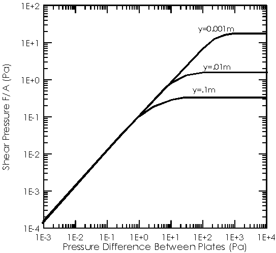
(1)When the mean-free-path is short compared to the characteristic dimensions of the system, l/d <<1, the flow is viscous. In this region, the viscous force (or drag) on a moving plate is independent of the pressure.
(2)When the mean-free-path is long compared to the system length, l/d>>1, then you are in the free-molecular flow regime. In this region of pressure (or gas density), the viscous drag between two moving plates is linearly proportional to the pressure.
(3)A third regions of gas-flow, Knudsen or transition flow, is often used to describe the region between these two limits.

Fig. 1: Viscous shear force between two parallel
plates in air at 22C, illustrating the two regions of gas flow.
The behavior of a vacuum system is characterised by the
three parameters P (pressure), S (volumetric flow), and Q (gas throughput).
P: pressure [Torr]
S: volumetric flow [liter/sec]
Q: throughput [Torr-liters/sec]
S is particularly useful, since most pumps are designed to have a constant volumetric flow rate over a wide range of pressures. For pumps, the quantity S is called the pumping speed. In the steady state, P, Q, and S are simply related by the simple formula,
Some useful conversions,
1 Torr-liter = 2.5 x 10¹⁹ molecules at 273K (P=nkT)
1 CFM (cubic foot/min) = 0.47 liter/sec
So, the throughput Q is some number of molecules (torr-liter)
per second.
Probably the most important number you want to know is
the ultimate (steady state) or base pressure. This will be determined by
the total pumping speed of your system, and the gas load imposed by outgassing
surfaces and other gas sources (like leaks), given by Q.
The complete pumping equation is

where V is the volume of the system. The Q should be from
all sources, and in a real system it may be time dependent. Let's look
at the simplest solutions of the vacuum equation.
-No pumping (S=0), just a closed chamber (like a light bulb) which has a constant gas load from outgassing and/or leaks.
P=(Q/V)t
-Negligible outgassing or other sources, Q=0. In practice, this corresponds to the case for Q<<SP, which happens when you start a pumpdown cycle from atmospheric pressure. The solution for Q=0 is also simple,
which is sometimes referred to as pumping of the "volume
gas". It corresponds to the case when the "volume gas" is
the only significant source of gas molecules.
Pumping law in the High and ultra-high vacuum
regions
After a sufficient time, the pressure will reach equilibrium,
and the pumping equation simplifies to the form shown earlier, P(t)=Q(t)/S(t).
In most practical cases, the pumping speed is a constant (but there are
important exceptions). What determines the ultimate pressure is the behavior
of the gas load over time.
For many surfaces that are suitable for UHV use, Q(t) decreases like 1/t .
As the pressure falls in the HV and UHV region the pressure should decrease linearly with time (no leaks!),
P(t2)=P(t1) (t1/t2).
Finally, the pumping speed of all pumps begins to drop,
and the outgassing rate reaches some minimum value, and the pressure reaches
a "base pressure" which can be related to some ultimate value
of Q and S,
Po=Qo/So.
The final base pressure will depend on system history: bake-outs and so forth.

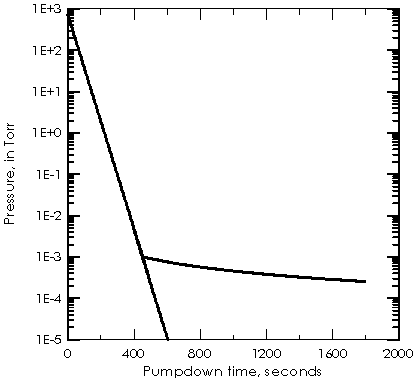
Fig. 2: Idealized initial pumpdown of a 100 l system, size 50 x 50 x 40 cm, with a 6 CFM roughing pump and 200 l/s UHV pump.
The very slow pump-down in the 1/t region is limited by
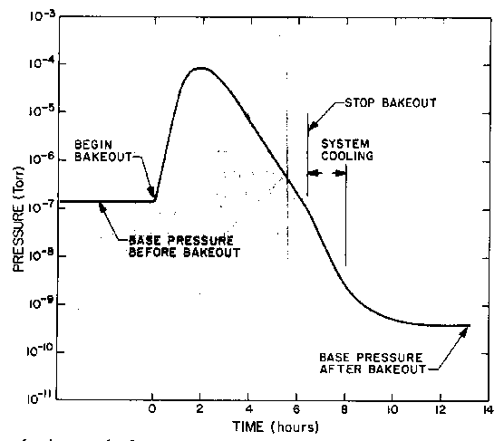
the outgassing of exposed surfaces. It is the reason that a bake-out of
the system is needed. The origin of the gas load is adsorbed gases. Some
examples of the scale of the problem:
Gas density in mol/cc is related to pressure in Torr by
n=3.3 x 10¹⁶P. If your vacuum system has 1 cc of volume for
each sq. cm of surface area, then since there are about 1015
molecules per cm2, putting a single monolayer into the vacuum would increase
the pressure by 3 x 10⁻² Torr (pretty big). If only 1 molecule
in 106 is in the gas phase at any time, the base pressure is
still only in the 8's. The adsorbed gases need to be removed.

Fig. 3: Typical pumpdown cycle.
Fig ?: Thermocouple gauge for roughing vacuum (molecular flow regime) measurements.
Fig ?: Thermocouple gauge output in milli-volts as a function of pressure,
1 to 1000 milli-Torr (x-axis is not labelled in conventional fashion)..

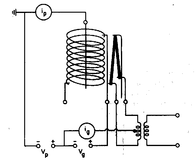
Fig ?: Diagram of an ion gauge for measuring UHV.
Ion gauge sensitivity is proportional to atomic number
Fig ?: Diagram of a typical diffusion pump. 4) condensor cones, 5)cooling
water lines 12)back-streaming baffles
There are two methods used for calculating pumping behavior
of a complex system, the addition of conductance method and the probabalistic
method (Oatley's method).
The basic idea is that the throughput of a physical restriction
is given by
Q = C (P2 - P1),
which defines the conductance C [l/s]. Conductance has
the same units as pumping speed.
This expression has the form of an 'Ohm's law' for vacuum,
where C is like 1/R, P is like volts, and Q is like current.
Like the electrical analog, physical elements in parallel
add their conductance,
CT = C1 + C2
+ ....
while conductances in series obey the law
Some practical cases for conductance, for air at room
temperature, with area A measured in cm2, and C in liters/second,
are
-Conductance of an aperture of area A,
C=11.6A
-Conductance of circular tube
C=12.1 D3/L
-Equivalent length of an elbow bent through an angle theta,

where D is the diameter of the tube.
(millibar-liter/sec-cm2)
| Fresh aluminum | 9 x 10⁻⁹ |
| Aluminum baked 20h at 100C | 5 x 10-14 |
| 304SS | 2 x 10⁻⁸ |
| 304SS electropolished | 6 x 10⁻⁹ |
| Teflon | 8 x 10⁻⁸ |
| Viton A (fresh) | 2 x 10⁻⁶ |
Materials which should be avoided
1. Improper cleaning techniques
2. Incompatible materials
3. Leaks
4. Virtual leaks
Generally, each pump will have its
own unique combination of strengths and weaknesses in terms of expense,
durability, pumping speed vs. pressure, residual gases, and ease of use.
1. Roughing pumps (1 atmosphere to 1-10 micron)
-Rotary vane (oil) mechanical pumps
low cost,durable, long life
high pumping speed
oil-backstreaming must be controlled
-Cryosorption pumps (sorption pumps)
very clean
inexpensive and simple
limited capacity, frequent reconditioning (baking)
-Molecular drag pumps
very clean
high pumping speed
very expensive
2. Diffusion pumps (high vacuum and UHV)
For UHV, includes LN2 trap and trapped rotary pump
Low cost per unit pumping speed, very high pumping speeds
Very well understood
Hard to destroy
Continuous operating expense (LN2)
Potential for serious vacuum accidents
"Open system":Forbidden in certain applications
3. Turbomolecular pumps (high vacuum and UHV)
For UHV, includes trapped rotary pump
Medium to high cost per unit pumping speed
Very clean, pumps rare gases
Easy to destroy
Requires periodic maintenance which can be expensive
Difficult to reach very low UHV base pressures
"Open system": Forbidden in certain applications
4. Titanium sublimation pumps (HV and UHV)
Very inexpensive and simple
Extremely high pumping speeds possible at high pressure
Requires periodic maintenance, which is cheap
Often misused, which limits their performance
Selective in what it pumps (good for Oxygen, N2, air, not for rare gases)
5. Cryopumps
Expensive per unit pumping speed
Very high pumping speeds are possible
Pumps hydrogen (pumps everything)
Requires periodic recharging
Vibration can be a serious problem
6. Ion pumps (also called sputter-ion pumps)
Expensive per unit pumping speed
Low pumping speed
Generates hydrocarbons
Has a memory effect
Very low maintenance
Moderately difficult to destroy
Excellent base pressures
Does not pump rare gases well
Does not pump hydrogen
Closed system: very safe against vacuum accidents
An 'ideal' UHV work-station today consists of several
types of pump used in different applications:
-a cryo-sorption pump or trapped rotary pump for initial pumpdown from atmosphere
-a turbo-molecular pump to pump rare gases, assist in initial pump-down, and to pump load-locks
-an ultra-high vacuum pump. Depending on the application, this can be an ion pump/Ti sublimation pump, a diffusion pump, or a cryopump.